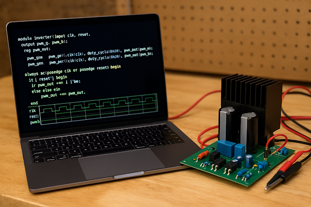
Verilog, although originally developed for digital circuits, has extended capabilities (through Verilog-A and Verilog-AMS) that make it a strong tool for modeling, simulating, and verifying power electronic systems. This article explores how Verilog is applied in power electronics, modeling techniques, examples, and best practices.
Why Use Verilog in Power Electronics?
-
Mixed-Signal Systems: Power electronics systems often blend analog (voltages, currents) and digital (controllers, logic) components.
-
Hardware Realism: Verilog models can simulate real-world hardware behavior at multiple abstraction levels (behavioral, RTL, structural).
-
FPGA/ASIC Development: For digital controllers (e.g., PWM generation, fault detection), Verilog enables FPGA/ASIC implementation directly.
-
System Integration: Verilog models can seamlessly interact with digital design workflows for full system-on-chip (SoC) or embedded systems.
-
Faster Prototyping: Quick simulations and verifications of designs before hardware fabrication.
Key Modeling and Simulation Techniques
1. Behavioral Modeling
-
Purpose: Fast simulation by representing the function without detailed internal structure.
-
Use: PWM generation, digital compensators, basic inverter logic.
Example: Basic PWM Generator in Verilog
module pwm_generator(
    input clk,
    input [7:0] duty_cycle,
    output reg pwm_out
);
reg [7:0] counter;

always @(posedge clk) begin
    counter <= counter + 1;
    pwm_out <= (counter < duty_cycle) ? 1 : 0;
end

endmodule
-
Explanation: This module generates a PWM signal based on an input duty cycle (0–255) and updates the output on every clock pulse.
2. Structural Modeling
-
Purpose: Represents the system using interconnections of smaller modules (hierarchical design).
-
Use: Modeling multi-stage converters, inverter bridges.
Example: Half-Bridge Inverter
module inverter_half_bridge(
    input clk,
    input enable,
    output reg top_switch,
    output reg bottom_switch
);

always @(posedge clk) begin
    if (enable) begin
        top_switch <= ~top_switch;
        bottom_switch <= ~top_switch;
    end else begin
        top_switch <= 0;
        bottom_switch <= 0;
    end
end

endmodule
-
Explanation: The top and bottom switches are toggled alternatively, ensuring dead-time and preventing shoot-through.
3. Mixed-Signal Modeling (Verilog-A/AMS)
-
Purpose: Model continuous analog behavior (voltages, currents).
-
Use: Modeling switching behavior, conduction losses, analog sensors.
Example: Ideal Switch Model in Verilog-A
`include "disciplines.vams"
module ideal_switch(p, n, control);
    inout p, n;
    input control;
    electrical p, n;
    logic control;

    analog begin
        if (control)
            V(p, n) <+ 0; // short circuit
        else
            I(p, n) <+ 0; // open circuit
    end
endmodule
-
Explanation: When
controlis high, the switch closes (voltage across it becomes 0). Otherwise, it behaves like an open circuit (zero current).
Best Practices
-
Abstraction Level: Choose the right abstraction level (behavioral vs structural) depending on simulation goals (speed vs accuracy).
-
Dead-Time Management: Always simulate dead-time in inverter models to prevent unrealistic short-circuit conditions.
-
Loss Modeling: Include conduction and switching losses where needed using Verilog-A constructs.
-
Multi-Domain Simulation: Use Verilog-AMS when co-simulating electrical, mechanical, and thermal behaviors.
-
Verification: Create robust testbenches to stimulate and validate your Verilog models under various operating conditions.
FAQs
Q1. Can Verilog fully replace SPICE for power electronics simulation?
Answer:
No. SPICE remains essential for detailed analog simulations (e.g., switching transients, parasitics).
However, Verilog and Verilog-A are excellent for system-level, mixed-signal, and digital control modeling where exact waveforms are less critical.
Q2. What is the difference between Verilog and Verilog-A?
Answer:
-
Verilog: Digital hardware description language (0s and 1s, event-driven).
-
Verilog-A: Analog extension of Verilog that models continuous voltages, currents, and analog behavior — ideal for power electronic components.
Q3. Can I simulate a full power converter (e.g., buck converter) using Verilog?
Answer:
Yes, using Verilog-A for the passive components (inductors, capacitors) and switches, and Verilog for the digital control (PWM, feedback loop).
Q4. What simulators support Verilog-A and Verilog-AMS?
Answer:
Popular options include:
-
Cadence Spectre AMS Designer
-
Mentor Graphics ModelSim with AMS Extensions
-
Synopsys VCS AMS
-
Xyce Analog Simulator
Some open-source options are emerging but are less mature for Verilog-AMS.
Q5. What skills are needed to model power electronics in Verilog?
Answer:
-
Good grasp of Verilog and optionally Verilog-A/AMS.
-
Solid understanding of power electronics principles (inverters, converters).
-
Experience with FPGA/ASIC tools if targeting hardware realization.
-
Knowledge of simulation environments and testbench development.
Conclusion
Verilog, especially when combined with Verilog-A and Verilog-AMS, is a powerful tool for modeling, simulating, and designing power electronic systems.
It enables engineers to not just simulate circuits, but to bridge the gap between analog power and digital control — a key aspect of modern systems like electric vehicles, renewable energy converters, and smart grids.
By carefully selecting the right modeling techniques and simulation strategies, engineers can accelerate their design cycles, improve system reliability, and innovate faster.


