There are several ways to control the speed of DC motors, but one of the easiest and most efficient methods is using Pulse Width Modulation (PWM). Before we dive into how PWM works, let's first understand how a DC motor operates.
How a DC Motor Works
The Permanent Magnet DC Motor (PMDC) is one of the most commonly used types of small DC motors. It provides continuous rotational speed that can be easily controlled, making it ideal for applications like toys, models, robots, and various electronic circuits requiring speed control.
A DC motor consists of two main parts:
- Stator – The stationary part of the motor that produces a magnetic field.
- Rotor (or Armature) – The rotating part that produces movement.
In smaller DC motors, the stator typically contains fixed permanent magnets that create a constant magnetic field. The rotor has coils of wire arranged in a circle around a metal core. These coils create alternating magnetic poles (north and south) as electric current flows through them, which in turn produces an electromagnetic field.
The interaction between the rotor’s magnetic field and the stator’s magnetic field causes the rotor to rotate.
Controlling Speed
The speed of a DC motor depends on the interaction between the magnetic field of the stator (the permanent magnets) and the field produced by the rotor’s electromagnets.
While the magnetic field from the stator is fixed and cannot be changed, we can control the strength of the rotor’s electromagnetic field by adjusting the current flowing through its coils. This changes the strength of the interaction between the two magnetic fields, which directly controls the speed of the motor.
The rotational speed of the motor (N) is related to the back electromotive force (emf, Vb) and the magnetic flux (Φ) produced by the permanent magnets. The relationship can be expressed by the equation:
Where:
- is the back emf (voltage),
- is the electromechanical constant,
- is the magnetic flux (which is constant for permanent magnet motors).
Traditional Speed Control Methods
In some cases, people try to control the motor speed by placing a variable resistor (called a rheostat) in series with the motor. While this method works, it’s not very efficient. The resistor wastes energy as heat, and a significant amount of power is lost in the process.
Pulse Width Modulation (PWM) for Speed Control
A more efficient way to control the motor’s speed is Pulse Width Modulation (PWM). PWM works by sending a series of electrical pulses to the motor that switch the power “ON” and “OFF” rapidly. The speed of the motor is controlled by adjusting how long each pulse is “ON” compared to how long it is “OFF.” This is known as the duty cycle.
- When the pulse is longer (more “ON” time), more average voltage is applied to the motor, and the motor will run faster.
- When the pulse is shorter (less “ON” time), less average voltage is applied, and the motor runs slower.
The key here is that PWM allows us to control the amount of power sent to the motor without wasting energy, as the transistor used to switch the power is either fully “ON” or fully “OFF.” This minimizes power loss and makes the control more efficient.
Another advantage is that the motor’s voltage remains constant, so it always operates at full strength, even at lower speeds, preventing it from stalling.
Generating the PWM Signal
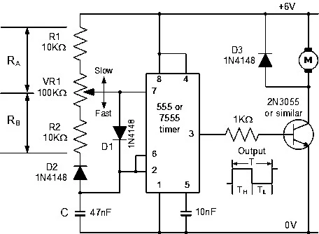
To generate the PWM signal, we can use an Astable 555 Timer Circuit. This circuit, based on the NE555 timer chip, generates the necessary pulses to control the motor’s speed.
The 555 Timer circuit works by charging and discharging a capacitor () through two resistors (RA and RB), which control the timing of the pulses. When the capacitor is charged, the output voltage switches “ON.” Once the capacitor is discharged, the output switches “OFF.”
The time it takes for the capacitor to charge and discharge depends on the values of the resistors and capacitor. This determines how long the pulse stays “ON” or “OFF.” By adjusting the values of , RB, and , you can control the duty cycle of the PWM signal.
For example, with the right values, the duty cycle can range from about 8.3% (short pulse) to 91.7% (long pulse) when using a 6V power supply. The frequency of the PWM signal (the rate at which it switches between “ON” and “OFF”) remains constant, typically around 256 Hz.
Protecting the Circuit
The circuit also includes a flywheel diode () to protect the electronics from the inductive load caused by the motor. This is important because motors generate high voltage spikes when the power is turned off, which can damage the circuit components.
Additionally, if the motor has a heavy load, it’s advisable to place a heat-sink on the switching transistor or MOSFET to prevent overheating.
Conclusion
Pulse Width Modulation (PWM) is a great method for controlling the speed of DC motors without wasting power. By adjusting the duty cycle of the PWM signal, you can easily control the motor’s speed efficiently. This same PWM technique can also be used for other applications, such as controlling the speed of a fan or dimming DC lights and LEDs.
If you need to control power in an efficient way, PWM is the solution.

%20Techniques%20for%20DC%20Motor%20Control%20and%20Power%20Conversion.png)


%20Techniques%20for%20DC%20Motor%20Control%20and%20Power%20Conversion.png)