Table of Contents
1. Understanding Substation Types
Substations can be classified based on their function and construction type. Some of the main types include:
- Transmission Substations: These substations step up or step down voltage for transmission over long distances.
- Distribution Substations: These handle the final step-down of voltage for distribution to consumers.
- Switching Stations: These stations do not involve voltage transformation but help control the flow of electricity.
The choice of substation type dictates the design, equipment, and protection systems needed.
2. Key Components of a Substation
The core components that need to be considered during the design process include:
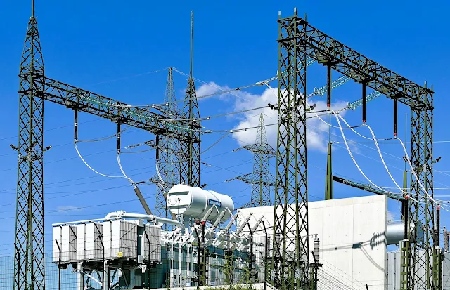
- Power Transformers: These are critical for stepping up or stepping down voltage levels. They are the most expensive and complex equipment in a substation.
- Circuit Breakers and Switchgear: These components are responsible for protecting the system by interrupting fault currents.
- Buses: Buses are conductors used to connect various parts of the substation and carry current from one equipment to another.
- Protection and Control Systems (P&C): This includes relays, IEDs (Intelligent Electronic Devices), SCADA systems, and other protection mechanisms that ensure the substation operates without failure.
3. Site Planning and Layout Design
Site Selection
The location of the substation plays a vital role in its design. Factors to consider include:
- Proximity to Load Centers: A substation should be located near the area it will supply power to minimize transmission losses.
- Geological Conditions: Soil stability and land topography are essential to plan for the foundations of the equipment.
- Environmental Impact: Environmental considerations, such as noise, electromagnetic fields, and wildlife protection, must be accounted for.
- Accessibility: Easy access for maintenance and emergency response is a must.
Substation Configuration
The configuration refers to how the equipment is arranged. Common configurations include:
- Single Bus: Simple and inexpensive but offers no redundancy.
- Double Bus: Offers better reliability by allowing one bus to remain in service if the other fails.
- Ring Bus: Provides higher flexibility by creating a loop in the substation.
- Breaker-and-a-Half: Typically used in large substations for enhanced reliability and flexibility.
Each configuration has advantages and disadvantages depending on the application and required reliability.
4. Calculations for Voltage Transformation
Designing the voltage transformation process involves several key calculations:
- Voltage Ratio: The voltage step-up or step-down ratio is determined by the transformer rating. The formula for voltage ratio Vr is:
For instance, for a 132 kV primary to 11 kV secondary transformation:
This means the transformer steps down the voltage by a factor of 12.
- Current Calculations: For power calculations, the current on the secondary side of the transformer is calculated as:
Where:
- P is the power in watts (W),
- Vsecondary is the secondary voltage in volts.
For a 100 MW substation with a 11 kV secondary, the current would be:
This indicates the size of the transformers and the required conductor ratings.
5. Grounding and Protection Design
Proper grounding is crucial to the safety and protection of the substation. The grounding system must ensure that any fault currents are directed safely to the earth to prevent equipment damage or hazardous conditions.
Grounding System Design
A typical grounding system includes a mesh of copper conductors installed in the ground around the substation. The resistance of the ground must be minimized to allow for efficient fault current flow. A grounding analysis involves determining the required resistance for safe operation, which can be calculated using formulas based on soil resistivity.
Where:
- R is the resistance,
- ρ is the soil resistivity,
- D is the distance between electrodes,
- r is the radius of the electrodes.
Protection Systems
Protection systems consist of relays, fuses, and circuit breakers. Fault currents, such as short circuits or overloads, are detected by the protection systems, which then disconnect faulty sections of the network.
6. SCADA and Communication Systems
SCADA (Supervisory Control and Data Acquisition) is essential for remote monitoring and control of the substation. It allows operators to:
- Monitor voltage, current, and power flow in real-time.
- Detect faults and trigger automated responses.
- Perform remote switching operations.
Telecommunication systems within the substation enable the transfer of data between the substation and the utility's central control room. This includes using fiber optics, microwave radios, or copper wire systems.
7. Final Design Considerations
Once the conceptual design has been finalized, the following detailed steps are taken:
- Foundation Design: Concrete foundations are designed to bear the heavy equipment, with specifications for material strengths, load-bearing capacities, and dimensions.
- Control House: The control house design, which houses the protection and control systems, will include electrical, HVAC, and telecommunication systems.
- Security Systems: Fencing, lighting, and surveillance cameras are essential to prevent unauthorized access and ensure safety.
8. Construction and Testing
The final phase of the design process involves the construction of the substation, followed by testing and commissioning. The testing process ensures all components function as expected under normal and fault conditions.
FAQs
- What is the purpose of an electrical substation?
- What are the main components of a substation?
- How are substation designs tested?


