
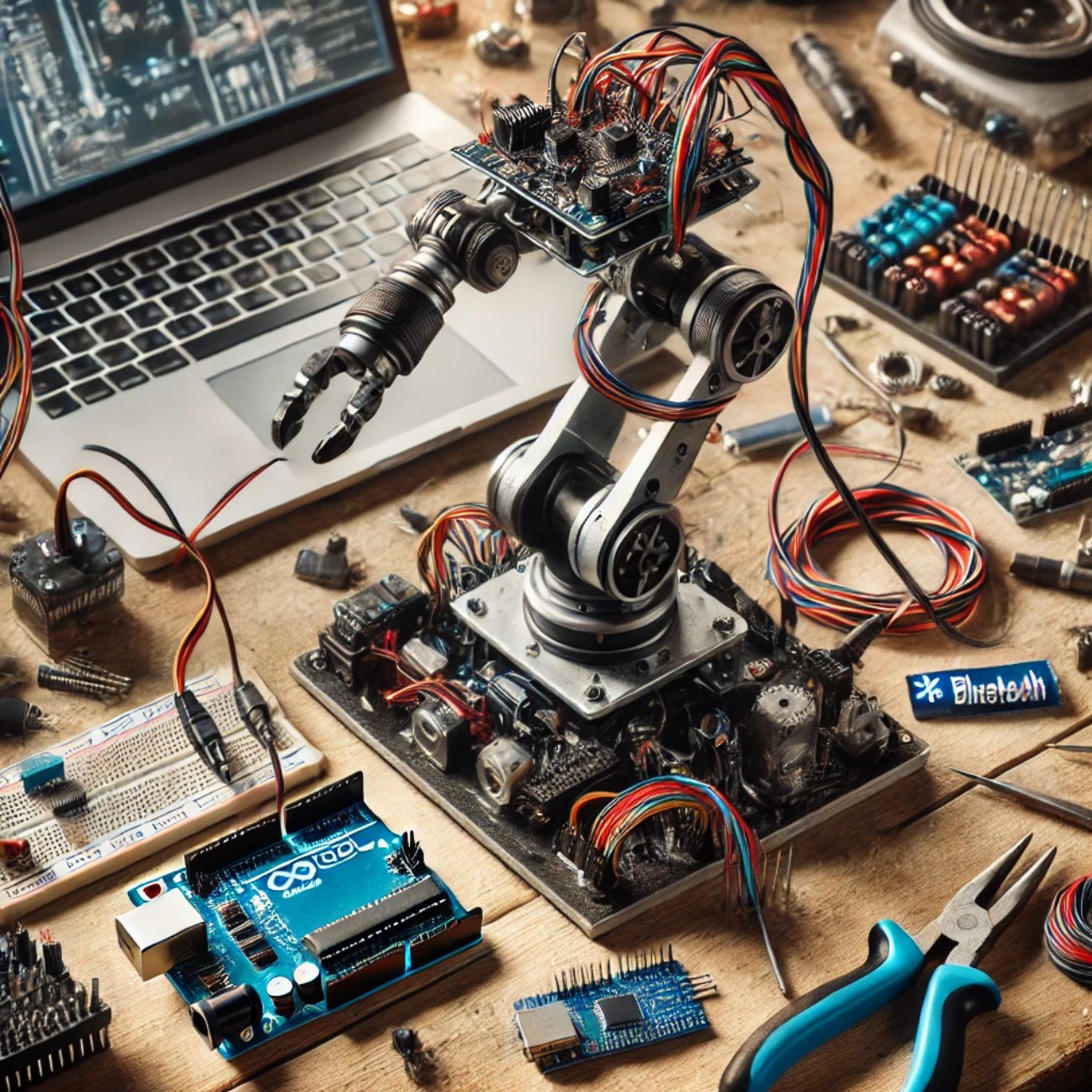
In this tutorial, I will guide you through the process of building a robotic arm that can be remotely controlled via programming using the Arduino Integrated Development Environment (IDE). This project is ideal for enthusiasts in robotics and mechatronics, and it provides hands-on experience with servo motors and Arduino programming.
Hardware Required
- Arduino Nano or Arduino Uno
- SG-90 micro servo motors (4 units)
- Robotic arm chassis (can be laser-cut or 3D printed)
- Jumper wires
- External power supply (for servos)
Software Required
- Arduino IDE (available for free download at Arduino Software)
Understanding the Robotic Arm
The robotic arm is a fundamental concept widely used in the robotics and mechatronics industries. Its applications range from manufacturing assembly lines to intricate tasks in research laboratories. Despite initial perceptions that building a robotic arm may be complex, a comprehensive understanding of its mechanics and the programming involved can simplify the process significantly.
Our robotic arm consists of four servo motors, providing a total of four degrees of freedom (DOF). The degrees of freedom indicate the number of independent movements the arm can perform, allowing it to reach various positions and orientations.

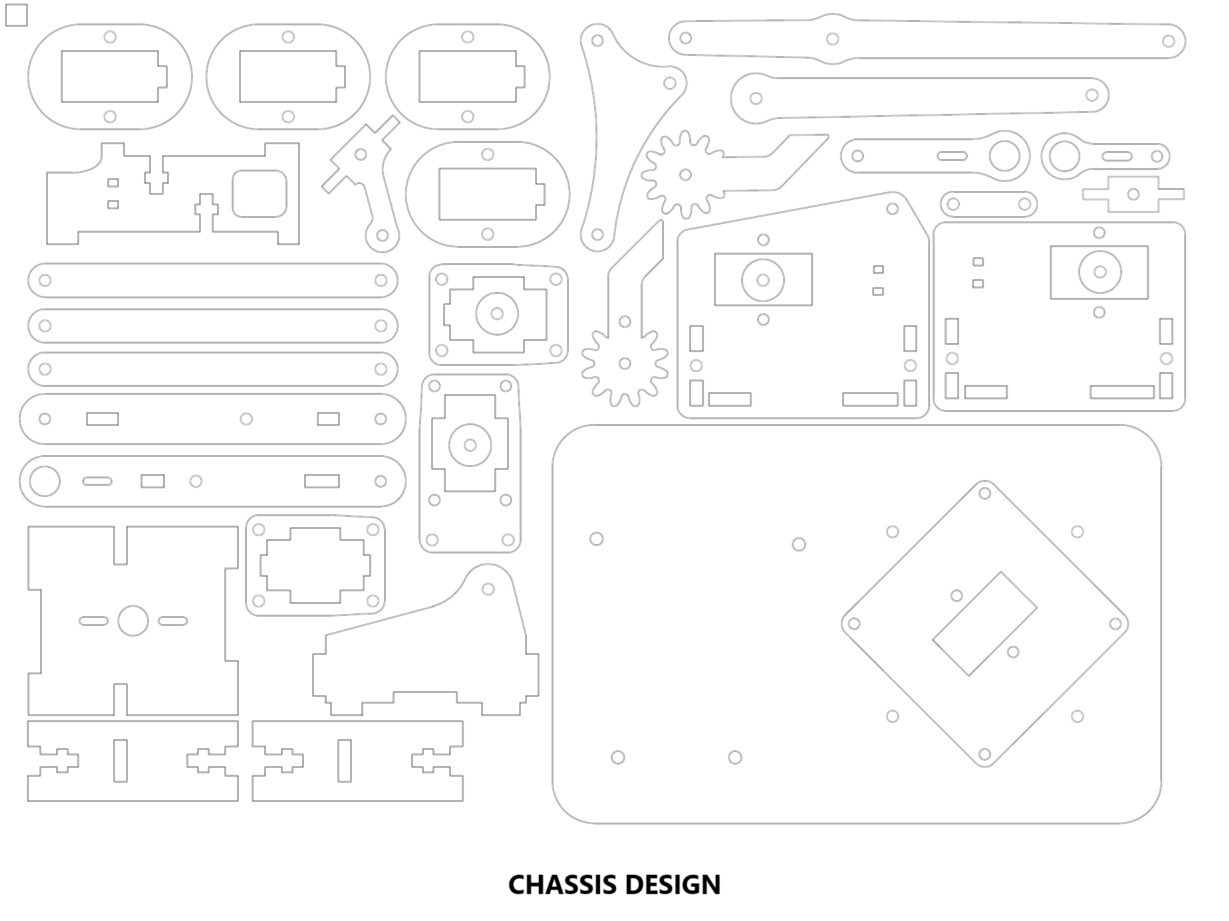
Chassis Design
The chassis serves as the structural framework for the robotic arm. Various designs are available online, with options for laser cutting from acrylic sheets or 3D printing from .stl files. For this project, we will use a chassis that can be laser-cut from a provided .dxf file. A proper assembly manual detailing the assembly process can typically be found alongside the chassis files, aiding in the construction of the robotic arm.
Wiring the Circuit
Connecting the servos and the Arduino is crucial for enabling control over the robotic arm. Here’s a breakdown of how to wire the components:
- Connect the signal wire of the base servo to pin 7 on the Arduino.
- Connect the signal wire of the shoulder servo to pin 9.
- Connect the signal wire of the elbow servo to pin 10.
- Connect the signal wire of the gripper servo to pin 11.
All positive terminals of the servos should be connected to an external power supply (typically 5V), while the negative terminals connect to the ground (GND) on the Arduino.
Circuit Diagram
Below is the circuit diagram of a remote-controlled robotic arm using Arduino:

Programming the Arduino IDE
Once the hardware setup is complete, the next step involves programming the Arduino using the Arduino IDE. Below is a simple code that allows you to control the robotic arm’s movements through predefined angles.
#include <Servo.h>

// Create servo objects
Servo baseServo;
Servo shoulderServo;
Servo elbowServo;
Servo gripperServo;

// Define pin connections
const int basePin = 7;
const int shoulderPin = 9;
const int elbowPin = 10;
const int gripperPin = 11;

void setup() {
    // Attach the servo pins to the servo objects
    baseServo.attach(basePin);
    shoulderServo.attach(shoulderPin);
    elbowServo.attach(elbowPin);
    gripperServo.attach(gripperPin);

    // Initialize servos to starting positions
    baseServo.write(90); // Center position
    shoulderServo.write(90); // Center position
    elbowServo.write(90); // Center position
    gripperServo.write(0); // Open position
}

void loop() {
    // Example movements (add your own logic here)
    baseServo.write(0); // Move base to 0 degrees
    delay(1000); // Wait for 1 second
    baseServo.write(180); // Move base to 180 degrees
    delay(1000); // Wait for 1 second
    shoulderServo.write(45); // Move shoulder to 45 degrees
    delay(1000); // Wait for 1 second
    shoulderServo.write(135); // Move shoulder to 135 degrees
    delay(1000); // Wait for 1 second
    elbowServo.write(30); // Move elbow to 30 degrees
    delay(1000); // Wait for 1 second
    elbowServo.write(150); // Move elbow to 150 degrees
    delay(1000); // Wait for 1 second
    gripperServo.write(90); // Close gripper
    delay(1000); // Wait for 1 second
    gripperServo.write(0); // Open gripper
    delay(1000); // Wait for 1 second
}
Code Explanation
The code starts by including the Servo library, which allows easy control of servo motors. We define four servo objects corresponding to the four motors in our robotic arm. The setup() function initializes the servo motors by attaching them to their respective pins and setting their starting positions.
The loop() function defines a series of movements for the robotic arm. It sequentially moves the base, shoulder, elbow, and gripper servos to specific angles, with delays to allow for the movements to complete before the next command is executed. You can customize the angles and timing based on your requirements.
Testing the Robotic Arm
After uploading the code to the Arduino, the robotic arm should respond according to the defined movements. Observe the movements and ensure all servos operate as intended. If any servo does not respond or moves erratically, check the connections and power supply to ensure everything is correctly set up.
Conclusion
Building a remote-controlled robotic arm using Arduino IDE programming is a rewarding project that offers insights into robotics and programming. With this basic setup, you can expand the functionality of the robotic arm by incorporating sensors, adding more servos for additional degrees of freedom, or even implementing wireless control through Bluetooth or Wi-Fi.
This project not only enhances your technical skills but also serves as a foundational platform for more advanced robotic applications.
