What is MOSFET?
A Metal Oxide Semiconductor Field-effect Transistor (MOSFET, MOS-FET, or MOS FET) is a type of field-effect transistor (FET) with an insulated gate. Its conductivity is controlled by the voltage applied to the gate. MOSFETs are used for switching or amplifying signals. The ability to change conductivity with the applied voltage is key to their function in amplifying or switching electronic signals.
Today, MOSFETs are more common than bipolar junction transistors (BJTs) in both digital and analog circuits. The gate of a MOSFET is formed by silicon dioxide, which provides isolation by preventing direct charge flow from the gate to the conducting channel.
MOSFETs are the most common transistors in digital circuits, with hundreds of thousands or millions included in memory chips or microprocessors. MOSFETs can be made with either p-type or n-type semiconductors. Complementary pairs of MOS transistors are used in CMOS logic circuits, which have very low power consumption.
Why MOSFET?
MOSFETs are particularly useful in amplifiers because their input impedance is nearly infinite, allowing them to capture almost all of the incoming signal. Their main advantage is requiring almost no input current to control the load current.
Structure
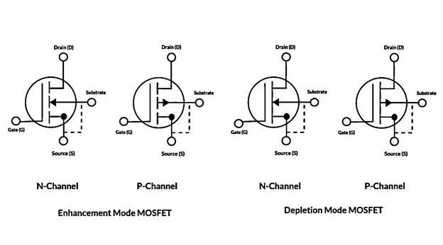
A MOSFET is a four-terminal device with Source (S), Drain (D), Gate (G), and Body (B) terminals. The Body is often connected to the Source, reducing the terminals to three. It operates by varying the width of a channel through which charge carriers (electrons or holes) flow. Charge carriers enter the channel at the Source and exit at the Drain. The width of the channel is controlled by the voltage on the Gate, which is insulated from the channel by a thin layer of metal oxide.
Types of MOSFET
MOSFETs operate in two modes:
- Depletion Mode: The transistor requires a Gate-Source voltage (VGS) to switch "OFF." It acts like a "Normally Closed" switch.
- Enhancement Mode: The transistor requires a Gate-Source voltage (VGS) to switch "ON." It acts like a "Normally Open" switch.
Based on their working principle, MOSFETs are classified into:
- P-Channel Depletion MOSFET
- P-Channel Enhancement MOSFET
- N-Channel Depletion MOSFET
- N-Channel Enhancement MOSFET
P-Channel MOSFET:
In a P-Channel MOSFET, the Drain and Source are heavily doped p+ regions, and the substrate is n-type. The current flows due to positively charged holes, hence the name p-channel MOSFET. Applying a negative gate voltage repels electrons beneath the oxide layer into the substrate, creating a depletion region of bound positive charges. This voltage also attracts holes from the P+ source and drain regions into the channel.
N-Channel MOSFET:
In an N-Channel MOSFET, the Drain and Source are heavily doped N+ regions, and the substrate is p-type. The current flows due to negatively charged electrons, hence the name n-channel MOSFET. Applying a positive gate voltage repels holes beneath the oxide layer, creating a depletion region of bound negative charges. This voltage attracts electrons from the N+ source and drain regions into the channel, forming an electron-rich channel.
MOSFET Working Operation:
The working principle of a MOSFET depends on the MOS capacitor, the main component of a MOSFET. The semiconductor surface beneath the oxide layer between the Source and Drain terminals can be inverted from p-type to n-type by applying positive or negative gate voltages.
Applying a positive gate voltage repels holes under the oxide layer into the substrate, creating a depletion region of bound negative charges. Electrons then form a channel. A voltage applied between the Drain and Source allows current to flow freely, controlled by the gate voltage. Applying a negative voltage forms a hole channel under the oxide layer.
Applications:
- Amplifiers
- DC Motor Regulation
- Chopper Amplifiers Construction
- Signal Switching and Amplification


