Table of Contents
- Introduction
- Basics of Transformers
- Working Principle
- Transformer Equations
- Types of Transformers
- Applications of Transformers
- Conclusion
- FAQ
Basics of Transformers
A transformer consists of primary and secondary coils (windings) and a magnetic core. The primary winding connects to the power source, while the secondary winding connects to the load. When alternating current (AC) flows through the primary coil, it generates a magnetic field, which induces a voltage in the secondary coil due to Faraday’s Law of Electromagnetic Induction. Transformers do not work with direct current (DC) as there is no changing magnetic field.
Working Principle
The working principle of a transformer is based on electromagnetic induction. When AC voltage is applied to the primary winding, it creates an alternating magnetic flux in the core. This changing magnetic field links to the secondary winding, inducing a voltage proportional to the turns ratio between the primary and secondary coils. This is described by the following equation:
Faraday's Law of Induction
The voltage induced in each coil is proportional to the rate of change of magnetic flux:
V = N × (dΦ/dt)
- V: Induced voltage in volts (V)
- N: Number of turns in the winding
- dΦ/dt: Rate of change of magnetic flux
Transformer Equations
Transformers follow specific equations that define the relationship between the primary and secondary windings.
1. Voltage Transformation Ratio
The voltage transformation ratio determines the change in voltage levels between the primary and secondary coils:
Vp / Vs = Np / Ns
- Vp: Voltage in the primary coil
- Vs: Voltage in the secondary coil
- Np: Number of turns in the primary coil
- Ns: Number of turns in the secondary coil
This ratio implies that for a step-up transformer (increasing voltage), Ns > Np, while for a step-down transformer (decreasing voltage), Ns < Np.
2. Current Transformation Ratio
The current in the primary and secondary coils is inversely proportional to their turns ratio:
Ip / Is = Ns / Np
- Ip: Current in the primary coil
- Is: Current in the secondary coil
Example Calculation
If a transformer has a primary coil with 100 turns and a secondary coil with 200 turns, and the primary voltage is 120V, the secondary voltage is calculated as:
Vs = Vp × (Ns / Np) = 120 × (200 / 100) = 240V
Types of Transformers
There are several types of transformers based on their purpose:
- Step-up Transformer: Increases voltage from primary to secondary.
- Step-down Transformer: Decreases voltage from primary to secondary.
- Isolation Transformer: Provides electrical isolation without changing voltage levels.
- Autotransformer: Shares primary and secondary windings, offering efficient design.
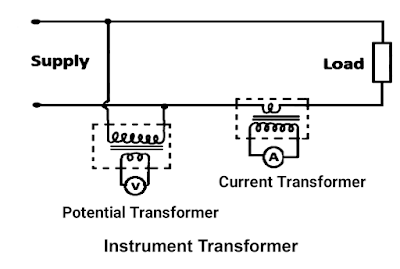
- Instrument Transformer: Measures high voltage and current values (e.g., current and potential transformers).
Applications of Transformers
Transformers have various applications across different fields:
- Power Distribution: Step-up transformers increase voltage for efficient long-distance transmission, while step-down transformers reduce voltage for safe home use.
- Electronics: Transformers are found in device chargers, adapters, and amplifiers to adjust voltage as required by electronic circuits.
- Industry: High-capacity transformers power industrial equipment, while instrument transformers aid in measurement and safety monitoring.
Conclusion
Transformers are vital devices in the electrical domain, enabling efficient power distribution and voltage regulation. They operate on the principle of electromagnetic induction, with primary and secondary windings and a core. Through their versatile designs, transformers serve various purposes, from power transmission to electronic device operation, making them indispensable in modern electrical systems.
FAQ
1. What is the main function of a transformer?
The main function of a transformer is to transfer electrical energy between circuits and adjust voltage levels as needed for power transmission, safety, and efficiency.
2. How does a transformer differ from a generator?
While a transformer transfers and transforms electrical energy between circuits, a generator converts mechanical energy into electrical energy for power supply.
3. Why don't transformers work with direct current (DC)?
Transformers rely on a changing magnetic field to induce voltage, which only occurs with alternating current (AC); DC does not produce the necessary fluctuating field.


